9 Turbines and Turbochargers
9.1 Definitions
Definition 9.1 (Turbine) A turbine is a rotating turbomachine that converts the drop in internal energy of a flowing fluid (liquid or gas) into mechanical rotational energy, which it delivers via its shaft. In an axial turbine the working fluid flows parallel to the shaft, in a radial turbine radially, i.e., perpendicular to the shaft.
Axial turbines are used in large engines, radial turbines in small engines.
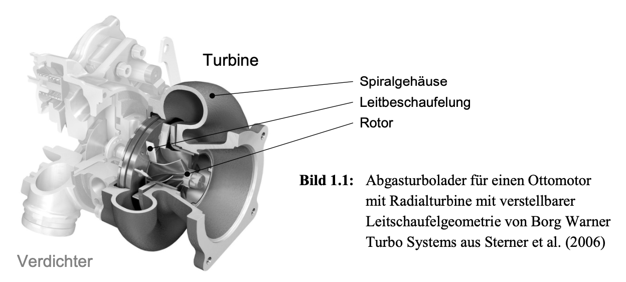
Definition 9.2 (Turbocharger) A turbocharger is a component for compressing the air supplied to an internal combustion engine (engine supercharging). It uses part of the energy of the engine exhaust gas by means of a turbine to drive a compressor, usually a radial compressor.
Figure 9.1 shows an exhaust gas turbocharger for a gasoline (Otto) engine.
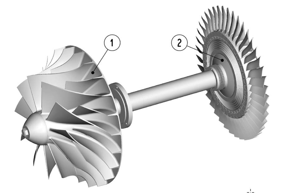
Definition 9.3 (Impeller and Rotor) An impeller consists of a ring of blades (vanes, rotor blades) that are held on the shaft by a suitable attachment. The totality of all impellers together with the connecting shaft is called the rotor.
A distinction is made between main blades and splitter blades. A rotor, including the compressor wheel, is shown in Figure 9.2.
9.2 High-Cycle and Low-Cycle Fatigue
Definition 9.4 (Low-Cycle and High-Cycle Fatigue) Material fatigue due to alternating loads is divided into low-cycle fatigue (LCF) and high-cycle fatigue (HCF). LCF describes the consequences of low-frequency, mostly thermal loads caused by changing operating states of the machine. HCF denotes damage caused by high-frequency dynamic loads resulting from vibrations.
Failure due to rotor vibrations is prevented by balancing and by sufficient damping in the plain bearings. Damage caused by blade vibrations is critical and unpredictable.
The interaction of the rotor blades with components of the housing or of the guide vane assembly gives rise to pulsating aerodynamic forces that induce a wide variety of bending and torsional vibrations of the blades.
The fluid-mechanical interaction of the guide vanes with the blades of the rotor produces high force amplitudes, which favor vibration excitation. In addition, the high excitation frequencies, which result from the number of guide vanes as a multiple of the rotational frequency, prove to be problematic. They fall into the range of the high natural frequencies of the stiff rotor geometry with its blades, which are relatively short compared with those of axial rotors. In the relevant frequency range, a typical rotor geometry has a large number of natural frequencies. On the other hand, in conjunction with the wide speed range in which turbochargers are operated, a broad excitation spectrum results. The consequence is a large number of possible resonance states within the operating range. Resonances are therefore unavoidable. To ensure a fatigue-resistant design of the rotor structure, critical resonant vibrations must be identified and their amplitudes must be predictable.
9.3 Natural Vibration Behavior of Turbomachines
Vibration investigations of turbomachines begin with a modal analysis of the rotor.
Definition 9.5 (Modal Analysis) Modal analysis determines the natural vibration behavior of a structure, i.e., its natural frequencies and the associated mode shapes, which are also referred to as modes.
The number of existing modes depends on the number of degrees of freedom of the vibrating system. For a continuum, theoretically infinitely many modes therefore exist. In the relevant frequency range, which follows from the excitation spectrum, a rotor usually has a finite number of modes. Knowledge of the natural frequencies and the associated modal deformations is the basic prerequisite for all further HCF investigations.
9.3.1 Blade and Disk Mode Shapes
9.3.1.1 The Behavior of a Single Blade
As shown in Figure 9.3, a blisk (blade integrated disk) consists of a disk and several blades. Axial blades can approximately be regarded as bending plates clamped at one end.
Each mode shape has an associated natural frequency, of which the one for the first bending mode takes the smallest value. Typically, the first torsion and the second bending mode form the next higher natural frequencies. With increasing frequency, a vibration referred to here as stiff bending occurs in the direction with the higher second moment of area. A longitudinal stretching of the blade, which is not shown, plays a subordinate role because it is not excited by aerodynamic excitation forces during operation.
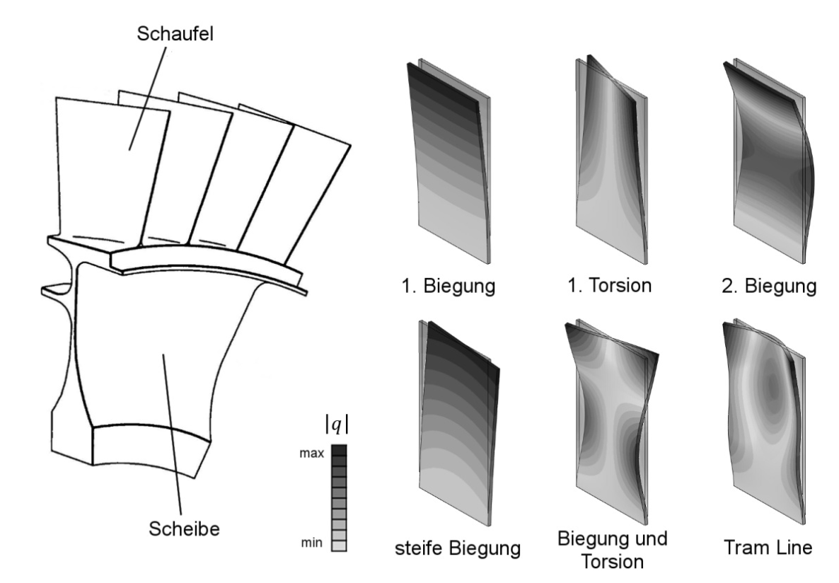
Higher modes are formed by the superposition of the shapes named first. The sequence of the natural frequencies depends on the dimensions. For the flat plate and also for a twisted plate, the natural frequencies and the modal shapes can be derived from an analytical solution of the vibration equation.
9.3.1.2 The Behavior of a Disk
The disk serves to absorb centrifugal forces and to transmit the torque to the shaft. It is shown in idealized form in order to illustrate typical disk mode shapes by means of nodal diameters and nodal circles.
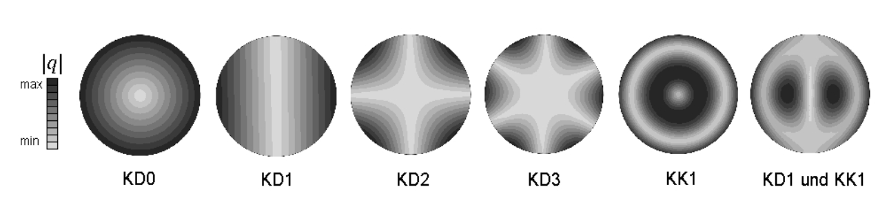
Definition 9.6 (Nodal Diameter and Nodal Circle) A nodal diameter (KD, from the German “Knotendurchmesser”; usually abbreviated ND in English) is a nodal line through the center of the disk along which the disk is not deformed. A nodal circle (KK) is a circular nodal line. The mode shapes are designated KD0, KD1, KD2, … according to their number of nodal diameters. KD0 is the homogeneous, in-phase displacement without nodal diameters.
These mode shapes are shown in Figure 9.4 for a disk of constant thickness clamped at its center. Mode shapes with nodal circles are relevant only for rotors with correspondingly slender disks. MacBain et al. (1979) compare the experimental generation of mode shapes with nodal diameters with the results of the finite element method (FEM).